Améliorations de l'AFFICHAGE et VARIATION de la vitesse
pour les rotors du type KR400 et 600
Dave Robinson WW2R, G4FRE
Introduction
For the
past 6 years in
A
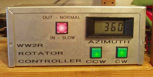
5 volt regulated supply is fed across the feedback potentiometer in the rotator.
The voltage produced by the wiper of the potentiometer is used, suitably scaled
to give 0 to 360 readout on a 200mV Full scale LCD meter unit.
To control the speed
of rotation of the rotator, the AC supply voltage to the primary of the
transformer, which drives the rotator motor is pulsed using a solid state AC
relay (RL1). The frequency (VR1) and width
(VR
Construction
The
original board obtained from DB6NT
needed physical modification to use components readily available in the
Firstly
determine accurately the direction of true North. Make sure SW1 is in the “full
speed” position. With the Left
(anticlockwise) switch turn the rotator until it points true North. Using VR3
set the LCD to read 000. With the Right (clockwise) switch turn the rotator 360
degrees until it points again exactly true North. Set VR4 to read 360 on the LCD
display. These settings are interactive so this process will need to be repeated
a couple of times to get exactly the correct LCD readings. VR1 and VR2 are
adjusted to give the required slow rotation speed with SW1
depressed
Conclusions
The unit was finished just in time for the ARRL 2002 September VHF contest (OK to be exact it was calibrated the morning OF the contest). The number of times that the beam heading was calculated, the antenna pointed at that direction and peaking the antenna on a signal resulted in no improvement in signal strength, even on 10GHz was amazing. Having the ability to point the antenna in exactly the same direction 12 hours apart, to have a second attempt to work the same station was also a revelation. It was well worth the effort in constructing the unit.
Table 1 Composants :
R1
68R
R2
27k
R3
680k
R4,
R5, R6
2k2 1W
R7
for 240V operation 4R7 5W
VR1
200k preset Bourns type 3329H (DK 3329H-204)
VR
VR3
10k 10Turn Bourns type 3
VR4
100R 10Turn Bourns type 3
C1,
C
C3,
C4
10uF 25V Tantalum
C5,
C6
1uf 25V Tantalum
C7
100uf 60V NON POLARISED
C8
3u3 ceramic
IC1
7809
IC2
7805
IC3
74HC00
D1
1N4518 (Shottky)
D2,
D3
100PIV 1A minature bridge rectifier (DK
DB10
D4,
D5, D6
IN4001
V1
120V Varistor
LCD
3.5 digit200mV FSD 5V supply
TR1
Toroidal transformer. Primary 2 x 120V Secondary 2 x 12V 1.1A (DK
TE62072)
TR2
PCB Transformer. Primary 2 x 120V Secondary 2 x 10V 0.3A (DK MT2111)
SW1
DPDT latching, integral LED holder (NKK LB26SKW01), Red Lens (NKK
AT419C)
SW2,
3
DPDT momentary, integral LED holder (NKK LB25SKW01) Green Lens (NKK
AT419F)
SW4
DPDT Mains rated.
LED1,
2
Minature Green LED
LED
3
Minature Red LED
RL1
Solid state relay CMOS drive (MP120D4, Newark 91F5736) (see text)
(DK
= Digikey; www.digikey.com)
Figure 1:Circuit Diagram

Figure 2:PCB
layout
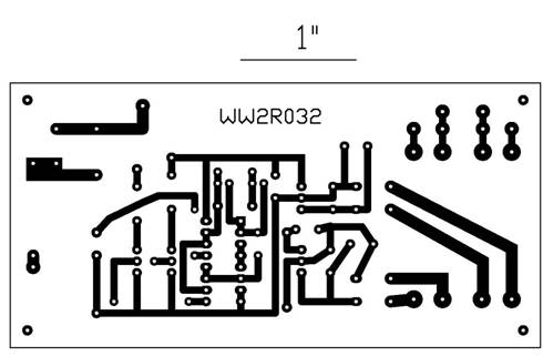
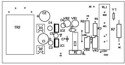
Figure 3: Component
Layout
derniére modif 18 January 2006